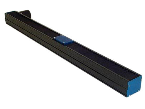
Voice Coil Positioning Stages (VCS and VMS)
The voice coil positioning stage is a compact, precise, and reliable positioning stage that can be used in various applications requiring high speeds and shorter strokes. The coil assembly has no magnetic attractive force, reducing the load on the bearing system and increasing the bearing life. It is ideal for closed-loop positioning applications like optical scanning, medical devices requiring quick and precise movement, or aerospace or industrial applications.
Linear Stepper Stages (LSS)
The linear stepper stage (LSS) is a compact, small-footprint, open-type positioning stage used in open or closed-loop positioning applications for lighter loads requiring high speed and acceleration. The low overall weight of the stage makes it ideal for a Y-axis in a multi-axis system, and an optional cable carrier is available to allow for high cycle count and passage of customer payload cables and hoses. This low-cost package has a short lead time for custom lengths and options.
Single Rail Brushless Linear Motor Stages (SRS)
The single rail positioning stage is a compact, small-footprint, open-type positioning stage. The stage works for closed-loop positioning applications that require high speed and acceleration of lighter loads. The stage has an ironless core coil assembly with no magnetic attractive force to the stationary magnet assembly, resulting in a smooth motion and increasing the life of the bearing system because of a reduced load. The low overall weight of the stage makes it ideal as a Y-axis (top axis) in a multi-axis system.
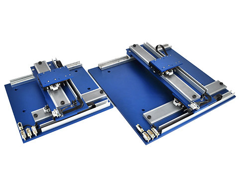
Dual Rail Brushless Linear Motor Stages (DRS)
The dual rail positioning stage is a low profile, wider footprint, enclosed positioning stage. It is used in closed-loop positioning applications that require high speed and acceleration of heavier loads. The dual parallel linear bearing rails with a minimum of four linear recirculating ball bushings provide a higher load-carrying capacity. The wide low profile of the stage ensures a stable platform for a payload or as an X-axis (bottom axis) of a stacked multi-axis system.
Crossed Roller Brushless Linear Motor Stages (XRS)
The crossed roller positioning stage is a compact, small cross-section open or enclosed stage for shorter stroke linear servo applications (up to twelve-inch stroke). Brushless linear motor powers the stage as two sets of parallel crossed-roller bearings guide the travel. The dual parallel rail sets offer the excellent load-carrying capability. The stage can be supplied with enclosed end covers and bellows. The small overall package size makes the XRS stage ideal as a Y or Z axis for short-stroke positioning applications.
Air Bearing Brushless Linear Motor Stages (ABS)
The air bearing positioning stage is a high-precision stage for high-end positioning applications. The drive mechanism for the stage is an ironless core, non-cogging three-phase brushless linear motor guided by flat magnetically preloaded air bearings floating on a granite base. The ironless core coil assembly results in a smooth motion. This type of stage has no wearing components in the system and is not limited to acceleration limits. The stiff cross-section of the granite base of the stage ensures a flat straight stable platform for the payload and does not require any special mounting considerations.
Belt Driven Stages (BLS)
The belt-driven stages are low-cost, durable positioning stages suited for either open or closed-loop operation. The stages can operate at a wide range of speeds from less than one one-thousandth of an inch per second to greater than one hundred inches per second. The standard offering of stages has travel lengths of up to 134 inches. Belt Stages are ideal for applications requiring precise positioning and fast speed. Stages can operate either horizontally or vertically and are available for multi-axis applications.
| |  |  |  |  |  |  |  |  |
| | VCS | VMS | | | | | | |
| | Moving Magnet | Moving Coil | | | | | | |
| Positioning Type | Closed Loop | Closed Loop | | | | | | |
| Continuous Force | 0.06-500 lbs (0.2-2224 N) | 0.12-419 lbs (0.5-1864 N) | | | | | | |
| Peak Force | 0.18-1755 lbs (0.8-7806 N) | 0.36-1257 lbs (1.6-5591 N) | | | | | | |
| Max Stroke | 2 in (76.2 mm) | 4 in (101.6 mm) | | | | | | |
| Max Velocity* | 50 ips (1.27 m/s) | 50 ips (1.27 m/s) | | | | | | |
| Max Acceleration* | 20 g's | 20 g's | | | | | | |
| Max Load Capacity* | 50 lbs (22.7 kg) | 50 lbs (22.7 kg) | | | | | | |
| Accuracy (Typ)** | +/-0.0007 in/ft (+/-58 µm/m) | +/-0.0007 in/ft (+/-58 µm/m) | (+/-58 µm/m) | (+/-58 µm/m) | (+/-33 µm/m) | (+/-16 µm/m) | (+/-500 µm/m) | (+/-58 µm/m) |
| Repeatability (Typ)** | +/-0.0004 in (+/-10 µm) | +/-0.0004 in (+/-10 µm) | (+/-10 µm) | (+/-7.5 µm) | (+/-5 µm) | (+/-2.5 µm) | (+/-100 µm) | (+/-10 µm) |
| Flatness (Typ)*** | +/-0.0012 in/ft (+/-100 µm/m) | +/-0.0012 in/ft (+/-100 µm/m) | (+/-100 µm/m) | (+/-66 µm/m) | (+/-41 µm/m) | (+/-8 µm/m) | (+/-165 µm/m) | (+/-66 µm/m) |
| Straightness (Typ)*** | +/-0.0013 in/ft (+/-108 µm/m) | +/-0.0013 in/ft (+/-108 µm/m) | (+/-108 µm/m) | (+/-74 µm/m) | (+/-41 µm/m) | (+/-8 µm/m) | (+/-108 µm/m) | (+/-66 µm/m) |
| Motor Type | Voice Coil | Voice Coil | | | | | Servo | Linear stepper |
| Bearing Type | Air, Ball, Linear, Cross Roller | Air, Ball, Linear, Cross Roller | | | | | | |
| Options | Custom Mountings, Custom Windings, Transducers | Custom Mountings, Custom Windings, Transducers | Multiple Slides, Compound Configurations | Multiple Slides, Compound Configurations | | Multiple Slides, Custom Mounting | Compound Configurations | Compound Configurations |
* = Max values depend on motor size and bus voltage available. Please contact factory to discuss application requirements.
** = Accuracy and repeatability values are dependant on feedback resolution. Please contact factory to discuss application requirements.
*** = Flatness and straightness values are typical values and will vary depending on the construction type and bearing selection.