These actuators are wound in such a way that no commutation is required for motion to occur. The result is a much simpler and more reliable system.
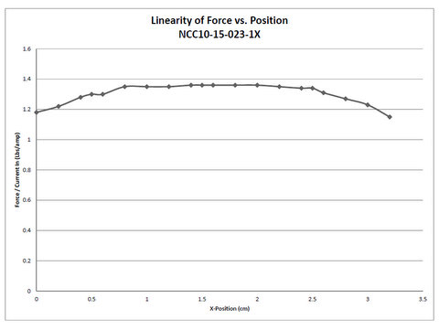
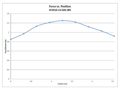
Coupling the actuators with a bearing system (if not supplied), position feedback device, linear servo amplifier and motion controller yields a system that is capable of intricate position, velocity, and acceleration control. These actuators can also be used for precise force control because of the linear force versus current characteristics.
Voice coil motors operate on the principal of the Lorentz force equation:
B = Flux density (Tesla)
I = Current (Amps)
Simply stated, a current carrying conductor placed in a magnetic field will have a force exerted upon it. This force is proportional to the direction and magnitude of the current and the flux density field. Since the permanent magnet flux density field is fixed, the direction of the linear displacement depends on the polarity of input current. The amount of force that is produced is directly proportional to the magnitude of the input current.
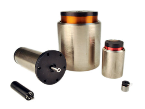
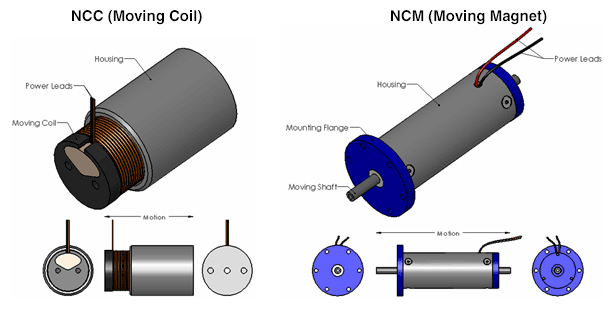
Our voice coil actuators are available in both standard as well as custom sizes. You can choose from either the moving magnet (NCM type) or moving coil type (NCC Type):
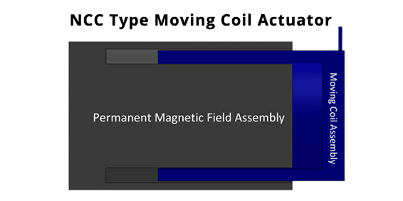
- The moving coil actuators, NCC Type (sometimes referred to as voice coils) are typically supplied without bearings or a shaft, but can be added if desired. They are generally larger in diameter and shorter in length. Higher forces can be achieved by increasing the diameter. This type of actuator can be designed with large radial clearances to ensure no contact between the coil and magnet assembly if a tilt or radial movement is required.
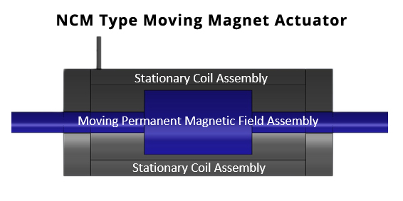
- The moving magnet actuators, NCM Type are supplied with bearings and a shaft. This type is generally smaller in diameter and longer in length. Higher forces can be achieved by increasing the number of poles, which increases the length, or by increasing the diameter. The main advantage is that there are no moving leads since the coil assembly is stationary. Optional no power magnetic latching is available at one or both ends of the stroke.
It should be noted that for both types of actuators, longer strokes are available but the efficiency or motor constant (Km) decreases as the stroke increases. This is due to the fact that the motor constant is inversely proportional to the stroke. If higher efficiency is desired for longer stroke actuators, the coil assembly can be wound as a multiphase coil and then it will have to be commutated.
Advantages:
- Small Size, High Force to Weight Ratio
- High Accelerations
- No Cogging or Commutation
- Custom Designs with Quick Turnaround Times
- High Flux Density Neodymium Magnets are Used
- Z Axis for Pick and Place Equipment
- Medical Diagnostic Probes and Laser Beam Steering
- Mirror Tilt and Focusing Actuators
- Miniature Position Control
Typical specifications for a non-commutated actuator are short stroke (0-3in or 0-75mm), accelerations of up to 20 times the acceleration due to gravity, continuous forces up to 100 lbs (0-100 lbs or 0-450N), peak forces up to 300 lbs (0-300 lbs or 0-1350N), and with the addition of a linear encoder or LVDT linear position resolutions down to 0.1 microns are acheivable.


Loading...
1.jpg)
Required Electronics:
Because of the very low inductance of the actuator, a DC linear servo amplifier is required to provide power to the Voice Coil. A programmable motion controller is required to close the position loop on the system.
Environmental Considerations:
The NC Actuators should not be mounted in an environment that is wet or excessively dirty or in an environment with ambient temperatures (>50ºC).
Mounting:
Mounting holes are provided on the housing, shaft and / or coil assemblies for mounting the actuator to customer supplied base and payload
Maintenance:
No maintenance is required.
(i.e. NCC05-15-020-2X is a moving coil actuator with 0.5" stroke, 1.5" OD, 2.0 lbs of continuous force, 2 pole magnet assembly and no special options)
NCC Moving Coil Type
General Description
Bi–directional DC linear motor consisting of a moving wound bobbin assembly and a stationary magnet assembly.
Construction:
Plated steel magnet housing assembly, nylon or like material wound bobbin assembly.
Your motor may or may not be supplied with a mounting flange or other mounting provisions refer to catalog BR1800 for standard motor specifications or refer to documentation included with shipment for custom motors.
Bearing type:
Bearings are not provided with standard models. It is the purchaser’s responsibility to supply bearings on standard models. With the magnet assembly secured, the bearing must support the bobbin assembly so that it is mechanically centered in the magnet assembly. Failure to center the coil assembly may lead to mechanical contact between the coil and magnet assembly. If this occurs, motor electrical shorts are possible. If your motor is supplied with bearings, refer to documentation included with shipment for additional information.
Maintenance:
Motor should be kept dry and relatively free of contamination. This motor is NOT WATER PROOF. Avoid submersion. Avoid contact with petroleum– based solvents. Alcohol can be used to remove contaminants.
Motor specifications:
Refer to catalog or outline drawing supplied with motor for mechanical dimensions and electrical specifications.
Motor Mounting:
Refer to catalog or outline drawing supplied with motor for mounting details and hole dimensions. If you motor is supplied with drilled and tapped mounting holes, refer to the recommended seating torque for screws in this document. It is recommended that a thread locking compound be used with mounting screws. Motor wires must be strain relieved.
Electrical Connections:
For voltage and current specifications, refer to product drawings or to documentation enclosed for custom motors. Your motor is supplied with 18 inch flying leads*. These wires can be cut to remove excess length if required. Connectors are available; contact a H2W representative for more information.
Motor Wire
| Function | Color |
|---|---|
| -DC | Black |
| +DC | White |
| Ground | Motor Housing |
* Some motors are supplied with custom cables; refer to documentation included with this shipment for any custom motor designs.
NCM Moving Magnet Type Non Commutated DC Linear Servo Motor
General Description:
Bi–directional DC linear motor with integral bearing.
Construction:
Anodized aluminum or plated steel housing, aluminum end–caps, steel center shaft. Your motor may or may not be supplied with a mounting flange or other mounting provisions refer to catalog BR1 800 for standard motor specifications or refer to documentation included with shipment for custom motors.
Bearing type:
Depending on motor catalog number the bearing may be one of the following: linear, anti rotational linear, rulon, sapphire, or flexure. Refer to catalog BR1 800. If your motor is custom, refer to documentation included with shipment. Maintenance: Motor should be kept dry and relatively free of contamination. This motor is NOT WATER PROOF. Avoid submersion. Disassembly of motor will void warranty. Avoid contact with petroleum based solvents. Alcohol can be used to remove contaminants.
Motor specifications:
Refer to catalog or outline drawing supplied with motor for mechanical dimensions and electrical specifications.
Motor Mounting:
Refer to catalog or outline drawing supplied with motor for mounting details and hole dimensions. When attaching payload to motor, avoid radial loading of the motor shaft. Radial loading can damage the bearing thus reducing its life. If your motor is supplied with drilled and tapped mounting holes, refer to the recommended seating torque for screws in this document. It is recommended that a thread locking compound be used with mounting screws.
Electrical Connections:
For voltage and current specifications, refer to product drawings or to documentation enclosed for custom motors. Your motor is supplied with 18 inch flying leads*. These wires can be cut to remove excess length if required. Connectors are available; contact a H2W representative for more information.
Motor Wire
| Function | Color |
|---|---|
| -DC | Black |
| +DC | White |
| Ground | Motor Housing |
| Thermal Switch(optional) | Orange and Blue pair |
*If your motor was supplied with custom cables; refer to enclosed documentation for any custom motor designs.

OPERATING A VOICE COIL MOTOR USING A FUNCTION GENERATOR
A voice coil motor can be oscillated at a set frequency in open loop operation using a function generator. See diagram 1 for operation flow.
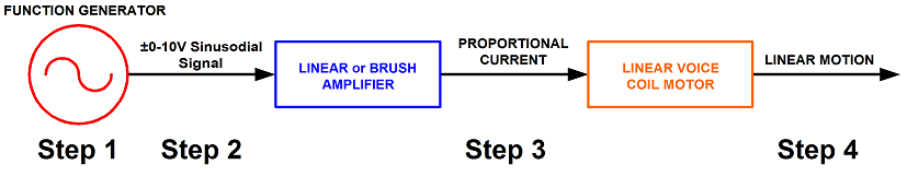
Step 1. A desired frequency and amplitude is set in the function generator.
Step 2. Based on the function generator settings, a +/- 10V reference signal is sent to the amplifier.
Step 3. The amplifier will take the reference input signal and provide the necessary current to oscillate the voice coil motor at the desired frequency. The amplitude of the frequency determines the displacement of the voice coil motor.
Step 4. The voice coil motor will oscillate at the desired frequency and displacement.
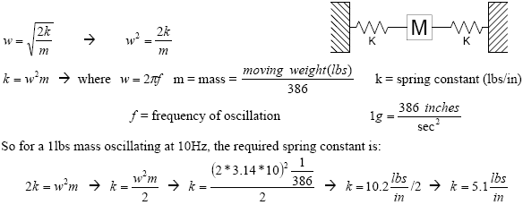
Note: 2 springs should be used with the motor to conserve energy and to provide a centering force for the moving magnet assembly of the voice coil.