The 3-phase coil assembly can be directly connected to the AC line for single speed applications or to an adjustable frequency drive for precise variable control of the speed of the motor. The motors are reversible and can also be dynamically braked.
The laminated coil assembly (shown above) is used in conjunction with a customer supplied aluminum and steel reaction plate to produce a force. A customer supplied bearing system is required to maintain the .040” - .060” [1 – 1.5 mm] air gap between the coil assembly and the reaction plate. The length of the reaction plate is equal to the coil length plus the stroke.
The amount of thrust produced by the LIM is proportional to the active surface area of the motor.
There is an attractive force between the coil assembly and the steel in the reaction plate only when power is applied to the coil assembly.
Multiple coil assemblies can used together to produce larger forces.
If the reaction plate is a disc, then rotary motion can be produced.
Either the LIM or the reaction plate can move while the other is fixed.
In hostile environments a non-magnetic stainless steel barrier can be used between coil assembly and the reaction plate to provide a seal.
Advantages:
- Only 2 parts
- Wide speed range
- No Maintenance
- Non-contact
- Ease of Control and Installation
Applications:
- Conveying Systems
- Cranes Drives
- Baggage Handling
- Vision Inspection Equipment
- Personal Rapid Transport Systems
- Theme Park Rides
The LIM consists of 2 main components:
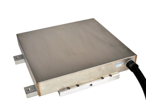
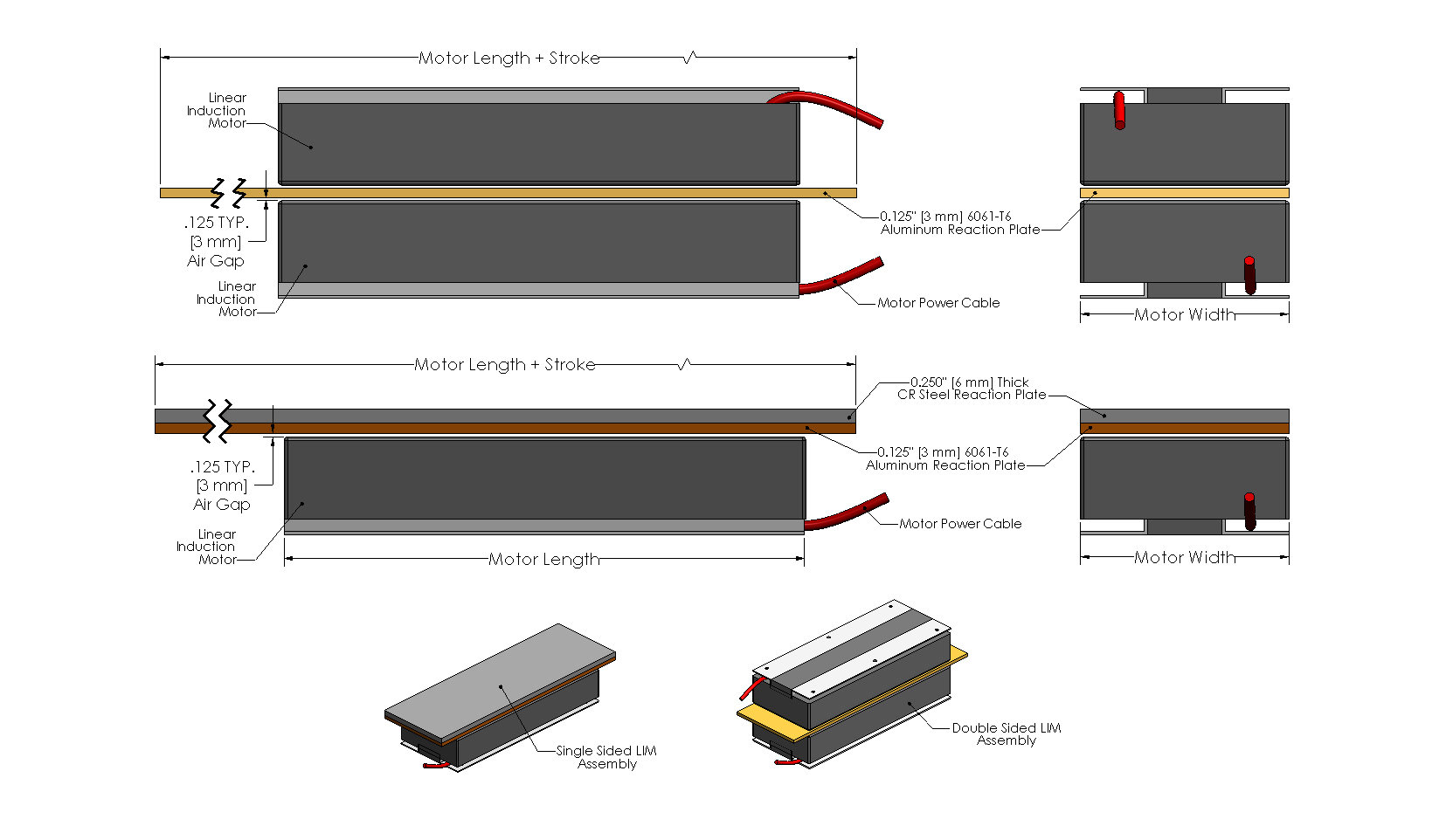
- 3 Phase Coil Assembly: The coil assembly is comprised of a 3-phase winding that is wound and inserted into a steel lamination stack with thermal protection devices. The entire assembly is then encapsulated with thermally conductive epoxy. Steel Angles with mounting holes are provided for mounting the coil assembly to the customers system. The coil assembly is available in many different widths and lengths, to meet the customers force and packaging requirements. The coil assembly can be used in a single sided or double-sided configuration. The single sided configuration consists of a single coil assembly that is used in conjunction with an aluminum plate backed by a steel reaction plate. The double-sided configuration is where 2 coil assemblies are facing each other, separated by a gap of .25” [6 mm] and only an aluminum reaction plate passes thru the gap. Multiple coil assemblies can be used together to produce larger forces. The standard sizes for the coil assemblies are shown on the following page
- Reaction Plate: The customer supplied reaction plate is required for proper operation of the LIM. The reaction plate is made up of standard, readily available 1018 steel, aluminum, and / or copper. For single sided operation, the required reaction plate consists of a .125” [3 mm] thick aluminum or a .080” [2 mm] thick copper plate that is backed by a .25” [6 mm] thick ferrous steel plate. The steel plate can be omitted but the force will be dramatically reduced. For double-sided operation only a conductive plate of copper or aluminum is required.
.svg)

Loading...
Required Electronics:
A 3-phase AC voltage directly from the line, an adjustable frequency supply, or a vector drive can be used to drive the LIM. The LIMs can be supplied for single phase AC, but the result is a less efficient motor. All standard voltages are available; 220, 380, 400, 415, 460, 600 @ 50 / 60 Hz
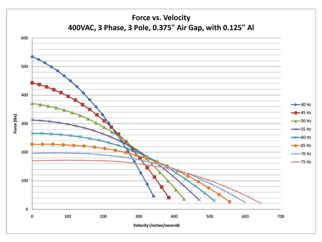
The speed of the LIM is proportional to the input frequency (which can be variable) and the pole pitch of the lamination stack (which is fixed). Connecting directly to the AC line at 50 or 60 Hz will produce a constant linear speed. Using an adjustable frequency drive (or inverter) will allow speeds as slow as 6 in/sec [0.15 m/s] and as fast as 1800 in/sec [45 m/s] at 400 Hz.
Mounting:
There are thru holes in the angles of the coil assembly for mounting to the customers system.
General Description:
Single or three phase, linear AC induction motor primary.
Construction:
Epoxy encapsulated and steel laminated coil assembly (motor primary) Motor secondary (customer supplied) must conform to the following specifications: 1/8–inch aluminum or copper plate backed by a 1/4 inch cold rolled steel plate. The width of the secondary must be at least the with of the motor coil assembly.
Maintenance:
Motor should be kept dry and relatively free of contamination. This motor is water resistant, not water proof. Avoid submersion. Avoid contact with petroleum–based solvents. Alcohol or soapy water can be used to remove contaminants.
Motor specifications:
Refer to catalog or outline drawing supplied with motor for mechanical dimensions and electrical specifications.
Motor Mounting:
Your motor may be supplied with either base or foot mounting, refer to catalog or outline drawing supplied with motor for mounting details and hole dimensions. It is recommended that all available coil assembly mounting holes be utilized to properly secure the coil assembly. If the coil is in motion, the motor wires must be strain relieved.
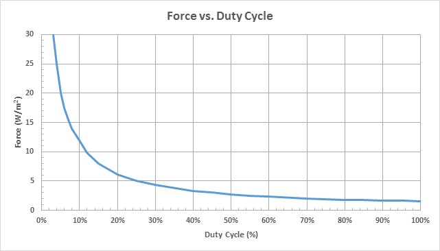
We recommend that the motor secondary be secured with 1/4inch fasteners on the left and right sides of the secondary, every four to six inches of its length. An air–gap of 1/8 inch is recommended. Refer to linear induction motor duty cycle–force–current curves in this booklet for information regarding the affects of air–cap size on motor performance.
Electrical Connections:
For voltage and current specifications, refer to Catalog BR1800 or to documentation enclosed for custom motors. The 10 foot flying leads can be cut to remove excess length if required. Connectors are available; contact a Baldor representative for more information.
For single phase motors, refer to the table supplied with this booklet for capacitor selection.
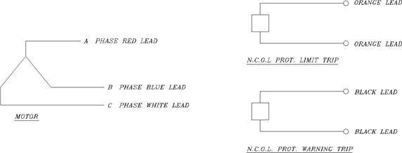
Motor Wire
| Function | Gauge | Color |
|---|---|---|
| PhaseA | 10 | Red |
| PhaseB | 10 | Blue(substituted by black in older models) |
| PhaseC | 10 | White |
| Ground | Motor housing | |
| Thermal Switch | 20 | Orange(two wires, interchangeable) |
| Thermal Warning | 20 | Black(two wires, interchangeable) |
LMAC Connection Diagram:


Step 1. The rated single or 3-phase AC voltage is applied to the linear induction motor.
Step 2. The linear induction motor will start from zero speed and accelerate to the rated velocity based on frequency and mechanical load.

Step 1. The rated single or 3-phase AC voltage is applied to the VFD.
Step 2. Based on VFD settings, a unique voltage and frequency is applied to the linear induction motor.
Step 3. The linear induction motor will start from zero speed and accelerate to the rated velocity based on frequency and mechanical load.