The ironless core coil assembly has no magnetic attractive force to the stationary magnet assembly, which reduces the load on and increases life of the bearing system.
The low overall weight of the stage makes it ideal as a Y axis (top axis) in a multi-axis system. The lower moving mass of the stage allows for much higher accelerations of light payloads.
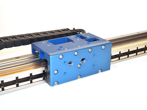
The cable carrier is oversized to allow for passage of customer payload cables and hoses. The back of the cable carrier can be easily removed and reattached to route through additional cables.
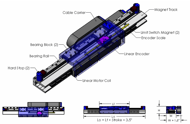
The SRS positioning stage incorporates the latest in linear motion technology:
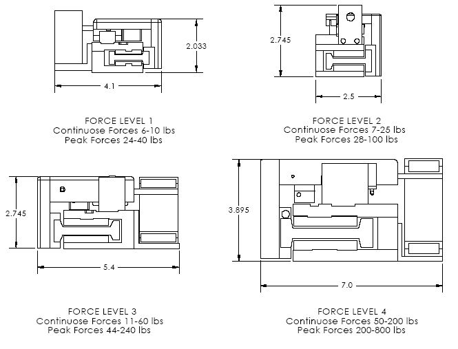
- Motors: non-contact 3 Phase Brushless Linear Motor, Ironless Core, commutated either sinusoidally or trapezoidally with Hall Effects. The encapsulated coil assembly moves and the multipole permanent magnet assembly is stationary. The lightweight coil assembly allows for higher acceleration of light payloads.
- Bearings: Linear guidance is achieved by using a single linear rail with 1 or 2 linear recirculating ball bearing guides. The bearing is sealed with wipers to contain the lubrication and to keep out debris.
- Encoders: Non-contact glass or metal scale optical linear encoders with a reference mark for homing. Multiple reference marks are available and are spaced every 50 mm down the length of the scale. Typical encoder output is A and B square wave signals but sinusoidal output is available as an option
- Limit Switches: End of travel limit switches are included at both ends of the stroke. The switches can be either active high (5V to 24V) or active low. The switches can be used to shut down the amplifier or to signal the controller that an error has occurred. The limit switches are typically an integral part of the encoder, but can be mounted separately if required.
- Cable Carriers: Cable guidance is achieved by using a cable carrier. Cable carriers are oversized to allow for routing of customers hoses and cables
- Bellows: The SRS does not come with bellows.
- Hard Stops: Hard stops are incorporated into the ends of the stage to prevent over travel damage in the event of servo system failure.
Advantages:
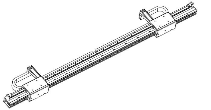
- Small Footprint and cross section
- Lowest weight per unit length
- Low cost
- High Acceleration of light loads
- High Speed
Applications:
- Pick and Place
- Vision Inspection
- Parts transfer
- Clean room


Loading...
| Flatness | ± 0.0012 in/ft | ± 100 micron/meter |
| Straightness | ± 0.0013 in/ft | ± 108 micron/meter |
| Accuracy* | ± 0.0007 in/ft | ± 58 micron/meter |
| Repeatability* | ± 0.004 | ± 10 micron |
| Load Capacity | 55 lbs | 25 kg |
Required Electronics:
The motor requires a 3 phase brushless amplifier with power supply, that is rated with sufficient current and voltage to meet the motion requirements. The inductance of the linear motor coil should be greater than the minimum load inductance of the servo amplifier. A programmable motion controller is required to close the position loop on the system.
Environmental Considerations:
The stage is a precision device with sensitive components, it should not be mounted in an environment that is wet or excessively dirty. The optical encoder scale is open and it should be kept free of debris in order to operate properly. The stationary magnetic assembly is highly magnetic, it should not be placed in an area where loose steel particles can be drawn into the magnetic gap. The stage must not be mounted in an environment with high ambient temperatures.
Mounting:
The stage should be mounted to flat and stiff surface. Counter bored thru holes are present in the stage to allow for the mounting of the stage to the customers system. The moving table assembly has threaded holes on the top surface for attaching the payload. The stage may be mounted in any orientation. When mounting the stage with the table moving vertical, it should be noted that the stage will be required to generate additional force due to gravity and that the stage will slide down to the bottom hard stop when power fails.
Maintenance:
The ball bearing guides in the stage should be periodically lubricated with the manufacturers recommended grease. The open glass encoder scale should be wiped with a glass cleaner occasionally to ensure trouble free operation.


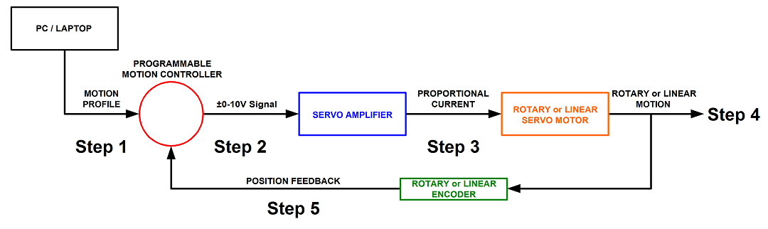
Step 1. A program or motion profile will be written on a PC or laptop and downloaded to the motion controller. This program will contain parameters such as speed, acceleration, deceleration, PIDs, desired position, etc…
Step 2. Based on the program parameters, the motion controller will send a +/- 10V reference signal to the servo amplifier.
Step 3. The servo amplifier will take the reference input signal and provide the necessary current to generate the required force from the motor to move to the desired position.
Step 4. The motor will move to the desired position at the programmed speed and acceleration.
Step 5: Motor position is sent back to the controller (typically 500 times per second) to verify that the desired position has been reached and maintained.