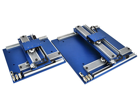
The linear stepper stage (LSS) is a compact, small footprint, open type, positioning stage. It can be used in either open loop or closed loop positioning applications that require high speed and high accelerations of lighter loads.
Should this motor be required to operate in an open loop application, you can control it with a step and direction signal from a standard microstepping drive. The power is supplied to the 2 or 4 phase forcer winding via a flexible cable. The full step is .010” [250 microns] for a 2 phase forcer and it can be microstepped down to .00004” [1 micron].
By integrating an optional linear encoder onto the single-axis linear stepper motor stage the linear stepper motor operates closed loop, as a 2-phase brushless linear motor, when coupled with state-of-the-art motion control electronics package provided by H2W. This allows H2W's stage to achieve speeds and accelerations previously unachievable with a linear stepper motor.
The short moving assembly called a “forcer” is guided by either roller or air-bearings along he precision ground track called a “platen”. The bearings are designed to support the customer’s payload and to maintain the required .001” [0.025 mm] gap between the platen and the forcer.
The low overall weight of the stage makes it ideal as a Y axis (top axis) in a multi-axis system. The lower moving mass of the stage allows for much higher accelerations of light payloads.
An optional cable carrier allows a high cycle count and is oversized to allow for passage of customer payload cables and hoses. The back of the cable carrier can be easily removed and reattached to route through additional cables.
This package is low cost, and has a short lead time for custom lengths and/or options.
The LSS series incorporates the latest in linear motion technology:
- Moving Forcer Assembly: The forcer is made up of an aluminum housing that contains the motor windings, lamination stacks, and permanent magnets. The active surface of the lamination is slotted to form teeth with a pitch of .040" [1 mm]. The ends of the coil are brought out to either a "D" connector or to flying leads. Mounting holes on the top surface of the forcer are for attaching the customer's payload. The forcer comes in different widths and lengths, depending on the required force. Multiple forcers can be supplied with a single platen to allow for independent moving heads.
- Long Stationary Platen: The platen is a precision ground steel bar or tube that is slotted to form .020" [0.50 mm] wide teeth on the surface. The bar is hard chrome plated and filled with epoxy to provide a flat air-bearing surface for the platen. The platen is available in widths from 1.25" to 3.0 " [31.8 mm to 76.2 mm]. The length of the platen is a function of the stroke. Single piece platens are available as long as 144 inches [3.6 m]. For longer strokes the platens will be supplied in sections.
- Encoders: Non-contact magnetic or metal scale optical linear encoders with a reference mark for homing.. Typical encoder output is a quadrature square wave signals A and B but sinusoidal output is available as an option.
- Limit Switches: End of travel limit switches can be included at both ends of the stroke. The switches can be either active high (5V to 24V) or active low. The switches can be used to shut down the amplifier or to signal the controller that an error has occurred. The limit switches are typically an integral part of the encoder, but can be mounted separately if required.
- Cable Carriers: Cable guidance is achieved by using a cable carrier. Cable carriers are over-sized to allow for routing of customers hoses and cables.
- Hard Stops: Hard stops are incorporated into the ends of the stage to prevent over travel damage in the event of servo system failure.
Advantages:
- Small Footprint and cross section
- Lowest weight per unit length
- Simple design provides trouble-free, precision control
- Low cost
- High Acceleration of light loads
- High Speed


Loading...
| Accuracy* | ± 0.0007 in/ft | ± 58 micron/meter |
| Repeatability* | ± 0.0004 in | ± 10 micron |
Operating info coming soon.
CLOSED LOOP LINEAR STEPPER POSITIONING STAGE

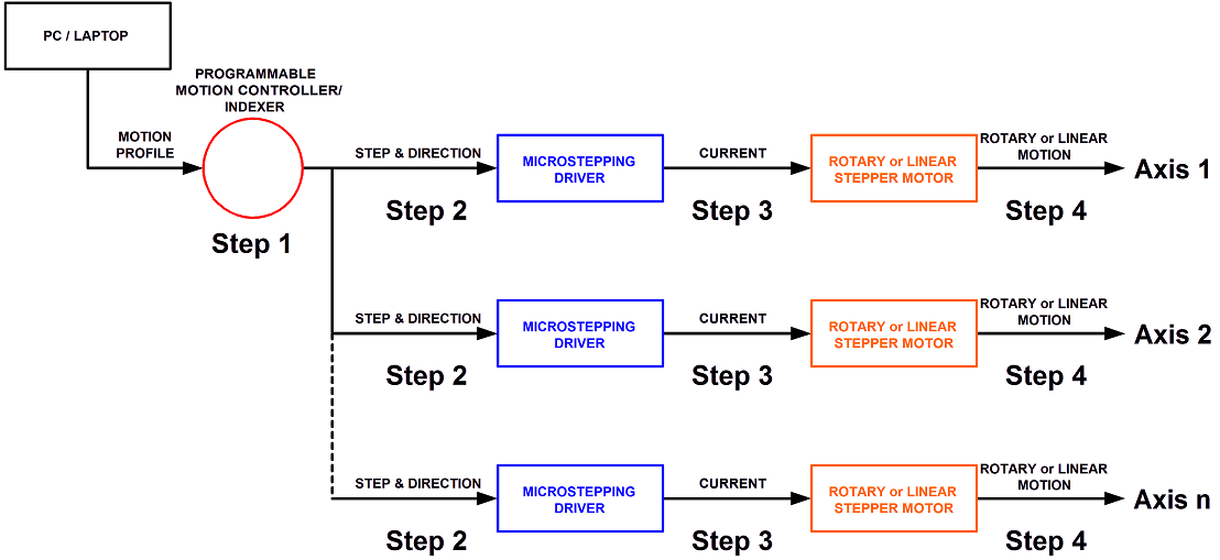
Step 1. A program or motion profile will be written on a PC or laptop and downloaded to the motion controller. This program will contain parameters such as speed, acceleration, deceleration, PIDs, desired position, etc…
Step 2. Based on the program parameters, the motion controller will send a +/- 10V reference signal to the servo amplifier.
Step 3. The servo amplifier will take the reference input signal and provide the necessary current to generate the required force from the motor to move to the desired position.
Step 4. The motor will move to the desired position at the programmed speed and acceleration.
Step 5: Motor position is sent back to the controller to verify that the desired position has been reached and maintained.
MULTI AXIS: LINEAR STEPPER MOTOR

NOTES:
-The program or motion profile will have specific parameters for each axis of motion. Parameters such as speed, acceleration, deceleration, desired move, etc… can be different for each axis.
-Depending on the particular motion controller/indexer used, the number of independent axis will vary from 2-32 axis of motion.
Step 1. A program or motion profile will be written on a PC or laptop and downloaded to the motion controller/indexer. This program will contain parameters such as speed, acceleration, deceleration, desired move, etc…
Step 2. Based on the program parameters, the motion controller/indexer will command the needed number of steps in the desired direction in order to move the motor the desired distance.
Step 3. The microstepping driver will take the step & direction input signals and move the motor using the drivers set current. The bus voltage of the microstepping driver determines the max motor speed.
Step 4. The motor will move the desired amount at the programmed speed and acceleration.


