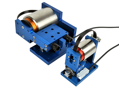
Their compact size allows them to fit into small spaces. They have very low electrical and mechanical time constants. The low moving mass allows for high accelerations of light payloads.
The ironless core coil assembly has no magnetic attractive force to the stationary magnet assembly, which reduces the load on the bearing system, which increases the life of the bearing. There are no magnetic drag forces (hysteresis), which allows for higher accelerations.
These actuators are wound in such a way that no commutation is required for motion to occur. Electrical devices such as Hall Effects are not necessary. The result is a much simpler and more reliable system.
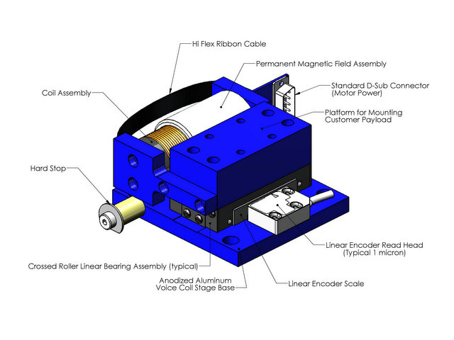
The VCS positioning stage incorporates the latest in linear motion technology :
- Motors: non-commutated moving coil (NCC) or moving magnet (NCM) voice coil motors.
- Bearings: Linear guidance and stiffness is achieved by using high precision ball slides or cross roller slides. Other types of bearings and bushings are available depending on the application.
- Feedback: Non-contact optical or magnetic linear encoders with a center reference mark for homing. Typical encoder output is A and B square wave signals but sinusoidal output is available as an option. Analog feedback is available via LVDT or Force Transducer.
- Limit Switches: Soft limits are typically used and monitored by the controller. But, if needed, end of travel limit switches may be included at both ends of the stroke. The switches can be either active high/low (5V to 24V). The limit switches can be used to shut down the amplifier or to signal the controller that an error has occurred. The limit switches can be an integral part of the encoder or can be mounted separately if required.
- Hard Stops: Hard stops are incorporated into the ends of the stage to prevent over travel damage in the event of servo system failure.
Advantages:
- Small Size, High Force to Weight Ratio
- High Accelerations
- No Cogging or Commutation
- Custom Designs with Quick Turnaround Times
- High Flux Density Neodymium Magnets are Used
- Low Cost Economical Solution
Applications:
- Mirror Tilt and Focusing
- Z Axis for Pick and Place Equipment
- Medical Diagnostic Probes and Laser Beam Steering
- Vision Inspection
- Miniature Position Control
- Clean room
11.svg)

Loading...

Required Electronics:
Because of the very low inductance of the actuator, a DC linear servo amplifier is required to provide power to the actuator. If a PWM amplifier is used, it is recommended to have a switching frequency of 50kHz or higher. A linear power supply is also recommended for better performance and noise reduction.
Environmental Considerations:
The stage is a precision device with sensitive components and should not be mounted in an environment that is wet or excessively dirty. The optical encoder scale is open and it should be kept free of debris in order to operate properly. The magnetic encoder scale should be kept away from any ferrous or magnetic materials. The magnetic assembly should not be placed in an area where loose steel particles can be drawn into the magnetic gap. The stage should not be mounted in an environment with ambient temperatures >50ºC.
Mounting:
The stage should be mounted to a flat and stiff surface. Counter bored thru holes are present in the base to allow for the mounting of the stage to the customers system. The moving slide assembly has threaded holes for attaching the payload. Custom mounting holes are available if the customer desires so. The stage may be mounted in any orientation. When mounting the stage with the slide moving vertically, it should be noted that the stage will be required to generate additional force due to gravity and that the moving slide will drop down to the bottom hard stop when power fails.
Maintenance:
The ball bearing guides in the stage should be periodically lubricated with the manufacturers recommended grease. The open encoder scale should be wiped down occasionally to clear it of any dust or particles to ensure trouble free operation.

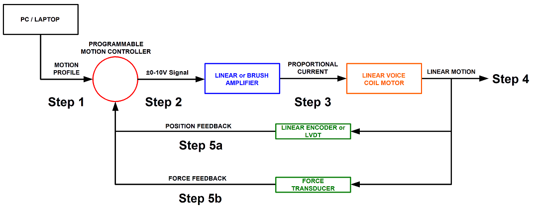
Step 1. A program or motion profile will be written on a PC or laptop and downloaded to the motion controller. This program will contain parameters such as speed, acceleration, deceleration, PIDs, desired position, etc…
Step 2. Based on the program parameters, the motion controller will send a +/- 10V reference signal to the amplifier.
Step 3. The servo amplifier will take the reference input signal and provide the necessary current to generate the required force from the motor to move to the desired position.
Step 4. The motor will move to the desired position at the programmed speed and acceleration.
Step 5: Motor position is sent back to the controller (typically 500 times per second) to verify that the desired position has been reached and maintained.
DUAL FEEDBACK - VOICE COIL POSITIONING STAGE

NOTES:
-The controller can only close the loop on one feedback device at a time. In this case it can close the loop on the position and monitor the force or close the loop on the force and monitor the position.
Step 1. A program or motion profile will be written on a PC or laptop and downloaded to the motion controller. This program will contain parameters such as speed, acceleration, deceleration, PIDs, desired position/force, etc…
Step 2. Based on the program parameters, the motion controller will send a +/- 10V reference signal to the servo amplifier.
Step 3. The servo amplifier will take the reference input signal and provide the necessary current to generate the required force from the motor to move to the desired position.
Step 4. The motor will move to the desired position or achieve the desired force at the programmed speed and acceleration.
Step 5a/5b: Motor position/force is sent back to the controller to verify that the desired position/force has been reached and maintained.


