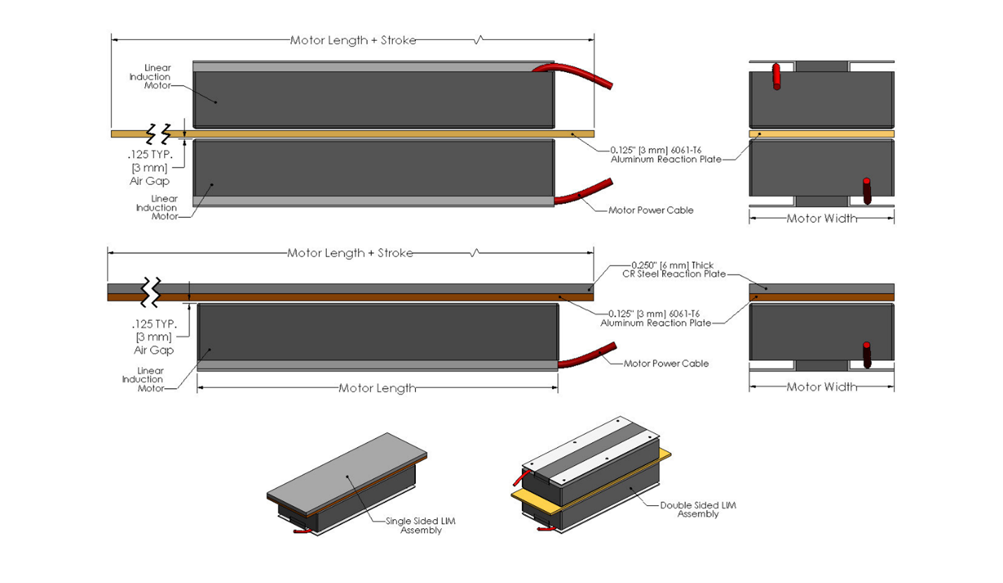
A linear induction motor has a primary or coil assembly and a secondary or reaction plate. The primary consists of three-phase coils wound and inserted into a steel lamination stack with thermal protection components. At the same time, the secondary or conductive reaction plate includes a combination of a conductive metal like aluminum or copper and a magnetic steel backing that interacts with a traveling electromagnetic flux wave generated by applied three-phase AC power. The wave induces an electric current in the conductive reaction plate. The induced electric current interacts with the magnetic flux producing linear force.
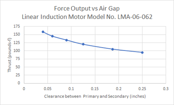
Typically, a bearing system gets designed to ensure a consistent gap between the primary and secondary. Maintaining a consistent gap will ensure a consistent force as Linear Induction Motors’ force will drop as the gap increases due to a reduction in the current induced in the reaction plate and a decrease in the magnetic field the further away from the lamination stack. Based on this premise, the secondary, ideally, would lie directly atop the primary. However, epoxy, varnish, or a case enclosing the primary coil assembly directs the user to have a more significant air gap, thus reducing the force.
A real-world experiment shows that the correlation between the clearance gap and the output thrust is nearly linear. Figure 1 below shows this relationship. The results are consistent with modeling and calculations with regard to this relationship.
Most LIM designs begin with a design parameter of an eighth-inch or three-millimeter clearance between the primary coil and secondary reaction plate. This design parameter offers a feasible starting point, accounting for clearance taken up by epoxy or a case. If a larger clearance gap is needed, then this should be directed to the manufacturer to determine if a LIM with greater thrust should be designed for your application.


