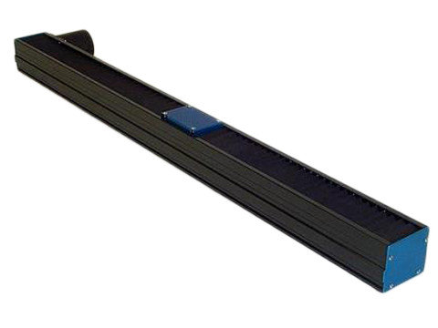
Stages can operate either horizontally or vertically and can be supplied in compound configurations for multi-axis applications.
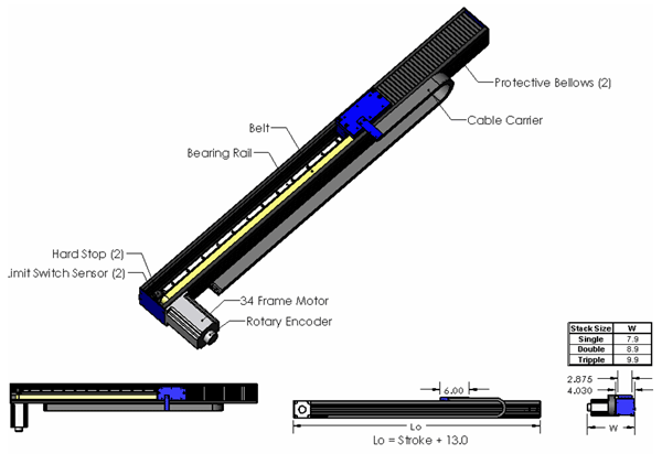
The BLS stage is offered with a bellows option (folded way covers) with a 12:1 extension to compression ratio. The bellows help to protect the belt and pulley mechanisms from contamination in dirty environments.
The BLS positioning stage incorporates the latest in linear motion technology.
- Motors: Depending on the system requirements, stepper, DC brush and brushless AC motors are available.
- Bearings: The table is supported by a standard guide wheel type linear bearing. A sealed recirculating ball linear bearing option is available for applications requiring precise motion of heavier payloads.
- Encoders: The stage can be supplied with an optional magnetic linear encoder with quaderature output.
- Limit Switches: Optional end of travel limit switches are available. The switches can be used to shut down the amplifier or to signal the controller that an error has occurred.
- Cable Carriers: For management of hoses and cables, a cable carrier option is offered.
- Bellows: Neoprene / nylon bellows with Mylar stiffeners are offered as an option and provide protection in harsh environments.
- Hard Stops: Hard stops are incorporated into the ends of the stage to prevent over travel damage in the event of system runaway.
Advantages:
- Quiet running, high speed
- Low cost
- Long life, low maintenance
- ELinear encoder option
- Cable carrier option
- Bellows option
- Two bearing options
- Motor mounts directly to the stage, no motor mounts required
Applications:
- Pick and Place
- Parts transfer
- Water Jet Cutting Machines
- Laser Cutting/Etching Machines
- Hi Speed Sewing Machines

| Flatness | ± 0.0008 in/ft | ± 67 micron/meter |
| Straightness | ± 0.0009 in/ft | ± 75 micron/meter |
| Accuracy* | ± 0.0007 in/ft | ± 58 micron/meter |
| Repeatability* | ± 0.0004 in | ± 10 micron |
| Load Capacity | 442 lbs | 200 kg |
Required Electronics:
Depending on the type of motor selected, a stepper indexer/driver can be
utilized for open loop step motor operation or a servo amplifier and
programmable motion controller can be utilized for closed loop servo motor
operation.
Environmental
Considerations:
The stage is offered with bellows, however care should be taken to protect
the stage from contamination and moisture. The stage is designed for
ambient temperatures to 45 º C.
Mounting:
The stage should be mounted to a flat and rigid surface. Mounting slots are
provided on the sides of the stage to allow for mounting to the customer’s
platform. The moving table assembly has threaded holes on the top surface
for attaching the payload. The stage may be mounted in any orientation.
When mounting the stage with the table moving in a vertical direction, it
should be noted that the stage will be required to generate additional
force due to gravity and that the stage will slide down to the bottom hard
stop when power fails. A motor brake is available.
Options:
- Bearings
- Guide wheel linear rail
- Recirculating ball linear rail
- Motors
- Stepper
- Brushless AC
- Brush DC
- Magnetic linear encoder
- Gear box
- Cable carrier
- Custom tapped holes for mounting of stage to customer’s platform
- Custom tapped holes in carriage for mounting of customer’s payload
Maintenance:
The ball bearing guides in the stage should be periodically lubricated with
the manufacturers recommended grease. The stage is supplied with an
integral springloaded belt tensioning system that may require periodic
adjustment. Tensioning is made easy by simply loosening and tightening two
adjustment screws on the outside of the stage body.
DUAL FEEDBACK - LINEAR MOTOR DRIVEN POSITIONING STAGE

NOTES:
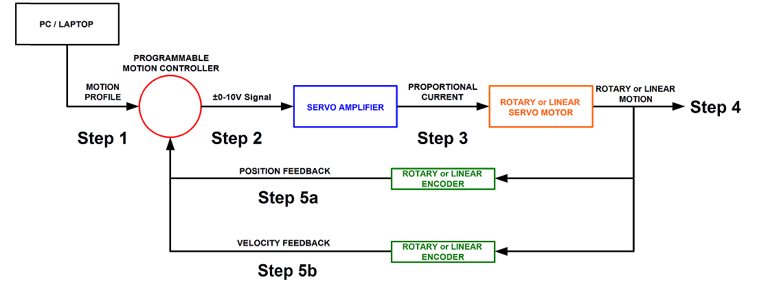
-The controller can only close the loop on one feedback device at a time. In this case it can close the loop on the position and monitor the velocity or close the loop on the velocity and monitor the position.
Step 1. A program or motion profile will be written on a PC or laptop and downloaded to the motion controller. This program will contain parameters such as speed, acceleration, deceleration, PIDs, desired position etc…
Step 2. Based on the program parameters, the motion controller will send a +/- 10V reference signal to the servo amplifier.
Step 3. The servo amplifier will take the reference input signal and provide the necessary current to generate the required force from the motor to move to the desired position.
Step 4. The motor will move to the desired position or achieve the desired velocity at the programmed acceleration.
Step 5a/5b: Motor position/velocity is sent back to the controller to verify that the desired position/velocity has been reached and maintained.


